
How to make a Bluetooth RC car By NodeMCU?
In this article, we talked about a Bluetooth RC car. That is how to make our own Bluetooth RC car using Nodemcu with the straightforward method. Let's make it.

Component Required:-
1.NodeMCU Board https://amzn.to/3TyqGaw
2.HC-05 Bluetooth Module https://amzn.to/3TwfScO
3.L298N Motor Driver Module https://amzn.to/3DhxIuT
4.12v DC Gear Motor https://amzn.to/3SlTXDW
5.12v (1.3Amp) Lithium Ion Battery https://amzn.to/3F1RICX
6.12v Blue LEDs https://amzn.to/3F0tEQN
7.3mm Red Led https://amzn.to/3F8UTZo
8. Buzzer https://amzn.to/3gm3jT3
9. Arduino Jumper wire https://amzn.to/3TAziwY
Schematics Diagram:-
This is a very simple schematic diagram. You follow this diagram step by step for making a Bluetooth RC car.

1.L298N Motor Driver is Connected to NodeMCU

Motor driver l298n of pin IN1 is connected to D0 / gpio(16) of node MCU board, and IN2 pin is connected to D1 / gpio(5) pin of node MCU, and motor driver IN3 is connected to D2 / gpio(4) and also pin IN4 is connected to D3 / gpio(0) of the node MCU board.
2. Front Light, Backlight, and Buzzer are connected to Node MCU:-

Here we are using 12v blue led for the front light of the RC car so we will need a bc 547 NPN transistor to control 12v led. If you use a normal 3mm led then you connect the direct (+) terminal of the led to gpio pin of node MCU. But here we want to lighter for the front light so we need a bc547 transistor for the external 12v power supply. BC 547 transistor of the emitter (E) pin is connected to the ground (GND) of node MCU and the base (B) pin of bc547 is connected 1st terminal of the 1k ohm resistor and the 2nd terminal of 1k resistor is directly connected to the D5 / gpio (14) pin of the node MCU board. And collector (C) pin is directly connected to the GND (-) terminal of the 12v blue led and Vcc (+) terminal is directly connected to the +12v of the battery. And for the horn, the (+) terminal of the buzzer is connected to the D6 / gpio(12), and the (-) terminal of the buzzer is connected to GND and also for the backlight of Bluetooth rc car, (+) terminal of led is connected to D7 / gpio(13) pin and negative (-) terminal is connected to all gnd pin of the circuit diagram.
2. HC-05 Bluetooth is connected to Node MCU:-

Code:-
/*Bluetooth RC Car Code*/
//L293 Connection
const int motorA1 = 16; //D0
const int motorA2 = 5; //D1
const int motorB1 = 4; //D2
const int motorB2 = 0; //D3
const int front_led=14; //D5
int horn=12; //D6
const int back_led=13; //D7
//Useful Variables
char state;
void setup() {
// Set pins as outputs:
pinMode(motorA1, OUTPUT);
pinMode(motorA2, OUTPUT);
pinMode(motorB1, OUTPUT);
pinMode(motorB2, OUTPUT);
pinMode(front_led,OUTPUT);
pinMode(back_led,OUTPUT);
pinMode(horn,OUTPUT);
// Initialize serial communication at 9600 bits per second:
Serial.begin(9600);
}
void loop() {
if(Serial.available() > 0)
{
state = Serial.read();
}
Serial.println(state);
/***********************Forward****************************/
//If state is equal with letter 'F', car will go forward!
if (state == 'F')
{
digitalWrite (motorA1,LOW);
digitalWrite(motorA2,HIGH);
digitalWrite (motorB1,LOW);
digitalWrite(motorB2,HIGH);
}
/**********************Forward Left************************/
//If state is equal with letter 'I', car will go forward left
else if (state == 'I')
{
digitalWrite (motorA1,LOW);
digitalWrite(motorA2,HIGH);
digitalWrite (motorB1,LOW);
digitalWrite(motorB2,HIGH);
}
/**********************Forward Right************************/
//If state is equal with letter 'G', car will go forward right
else if (state == 'G')
{
digitalWrite (motorA1,LOW);
digitalWrite(motorA2,HIGH);
digitalWrite (motorB1,LOW);
digitalWrite(motorB2,HIGH);
}
/***********************Backward****************************/
//If state is equal with letter 'B', car will go backward
else if (state == 'B')
{
digitalWrite (motorA1,HIGH);
digitalWrite(motorA2,LOW);
digitalWrite (motorB1,HIGH);
digitalWrite(motorB2,LOW);
}
/**********************Backward Left************************/
//If state is equal with letter 'J', car will go backward left
else if (state == 'J')
{
digitalWrite (motorA1,HIGH);
digitalWrite(motorA2,LOW);
digitalWrite (motorB1,HIGH);
digitalWrite(motorB2,LOW);
}
/**********************Backward Right************************/
//If state is equal with letter 'H', car will go backward right
else if (state == 'H')
{
digitalWrite (motorA1,HIGH);
digitalWrite(motorA2,LOW);
digitalWrite (motorB1,HIGH);
digitalWrite(motorB2,LOW);
}
/***************************Left*****************************/
//If state is equal with letter 'L', wheels will turn left
else if (state == 'L')
{
digitalWrite (motorA2,HIGH);
digitalWrite(motorA1,LOW);
digitalWrite (motorB2,LOW);
digitalWrite(motorB1,HIGH);
}
/***************************Right*****************************/
//If state is equal with letter 'R', wheels will turn right
else if (state == 'R')
{
digitalWrite (motorA2,LOW);
digitalWrite(motorA1,HIGH);
digitalWrite (motorB2,HIGH);
digitalWrite(motorB1,LOW);
}
/************************Stop*****************************/
//If state is equal with letter 'S', stop the car
else if (state == 'S')
{
digitalWrite(motorA1, 0);
digitalWrite(motorA2, 0);
digitalWrite(motorB1, 0);
digitalWrite(motorB2, 0);
}
else if(state == 'W')
{
digitalWrite(front_led,HIGH);
}
else if(state == 'w')
{
digitalWrite(front_led,LOW);
}
else if(state == 'U')
{
digitalWrite(back_led,HIGH);
}
else if(state == 'u')
{
digitalWrite(back_led,LOW);
}
else if(state == 'V')
{
digitalWrite(horn,HIGH);
delay(1000);
digitalWrite(horn,LOW);
delay(200);
digitalWrite(horn,HIGH);
delay(200);
digitalWrite(horn,LOW);
delay(1000);
}
else if(state == 'v')
{
digitalWrite(horn,LOW);
}
}
1. Open the Arduino IDE and go to the new file and paste the code.

2. And again go to the file click on it and go to the preference and click on it. And copy the JSON file and paste and ok. https://arduino.esp8266.com/stable/package_esp8266com_index.json

3. And go to Tools and click on it. and go Board then go Boards Manager.

4. And type esp8266 in the search bar and select 2.5.2 install and close.

5. And after installing the board we will need to driver install cp210x. So let,s install the driver first. Go to the driver file and open the file and install x64 bit.


6. After installing the driver. Now NodeMCU connects to the USB port of the computer and again go to the Arduino ide and go to the Tools and go to the Board and go to Boards Manager and choose NodeMCU 1.0.

7.And goto the Port and select COM4

8. firstly remove the hc-05 Bluetooth then upload the file.
9. Upload the code.

Pair The HC-05 Bluetooth Module into Smart Phone:-
1. 1st it should be ON HC-05 Bluetooth then you can pair and connect the robot to a smartphone successfully
2. Go to the Setting of the smartphone.

3. Open the setting and go to Bluetooth and open.
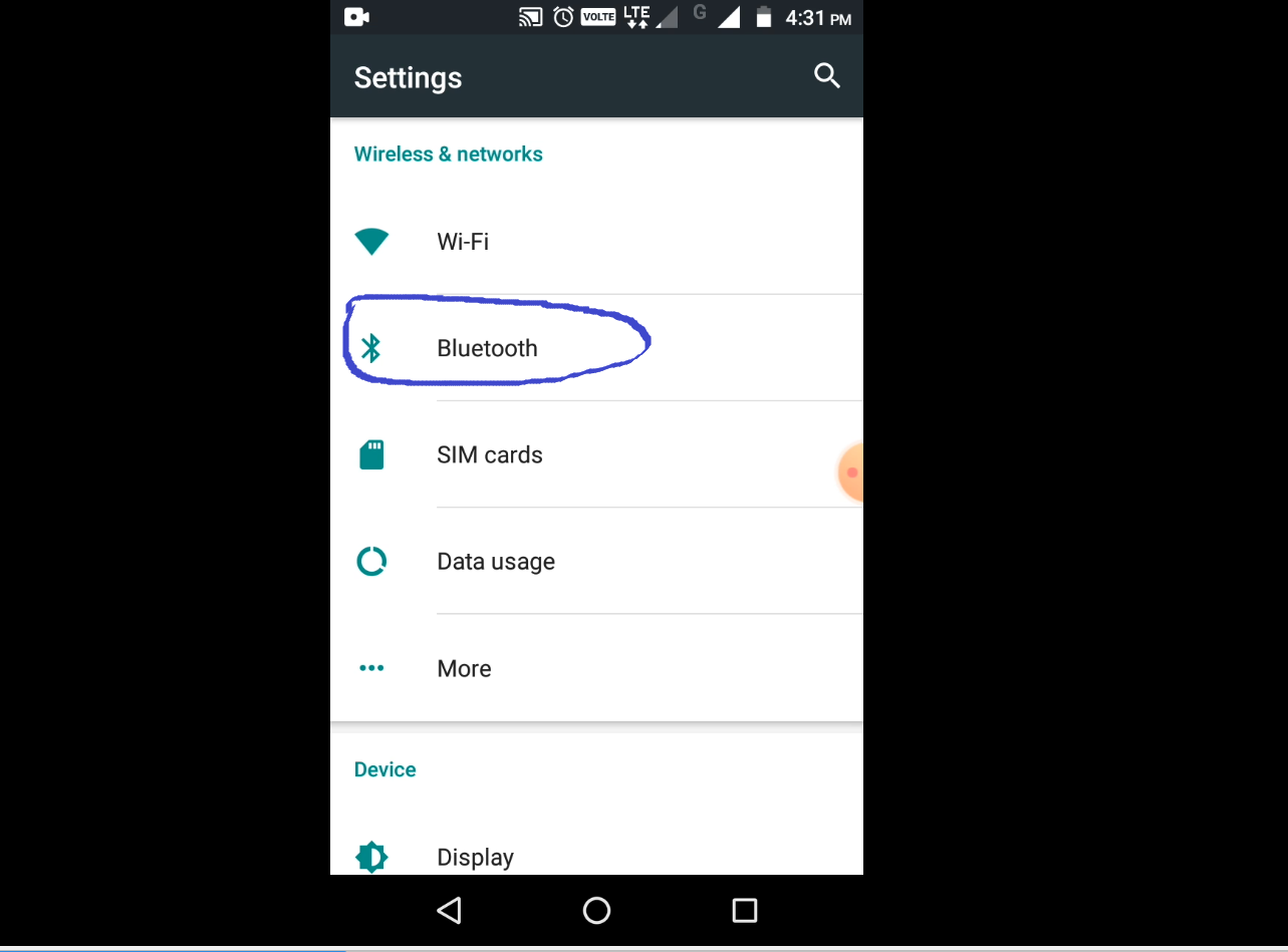
4. After opening the Bluetooth file, ON the Bluetooth device of the phone.

5. Then after a few seconds show all available Bluetooth lists. But here select only hc-05 Bluetooth.

6. After selecting the hc-05 then after we have to do pair so type 1234 and ok.


Download Bluetooth RC Car App from Play Store:-
1. Open the Smartphone and go to the play store.
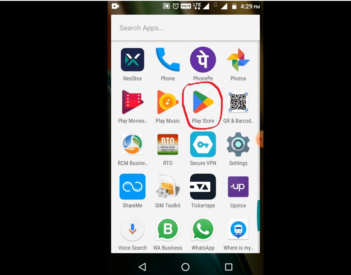
2. And go search bar and type Bluetooth RC car.

3. And then show the Bluetooth RC car app then click on and install it.


4. Open the App and allow the app.

5. After allowing the app then go to the options menu and open it.

6. After opening the Option menu then open the settings.

7. Then set this option and ok.


8. Then again go to the option menu and click on Connect to car.

9. After clicking on it then show all available names of the Bluetooth list but here ensure and select our hc-05 Bluetooth then the red led status changes to green led after hc-05 bt then connected from your smartphone to the robot and then you control the robot.


0 Comments